319,00€
Price VAT included

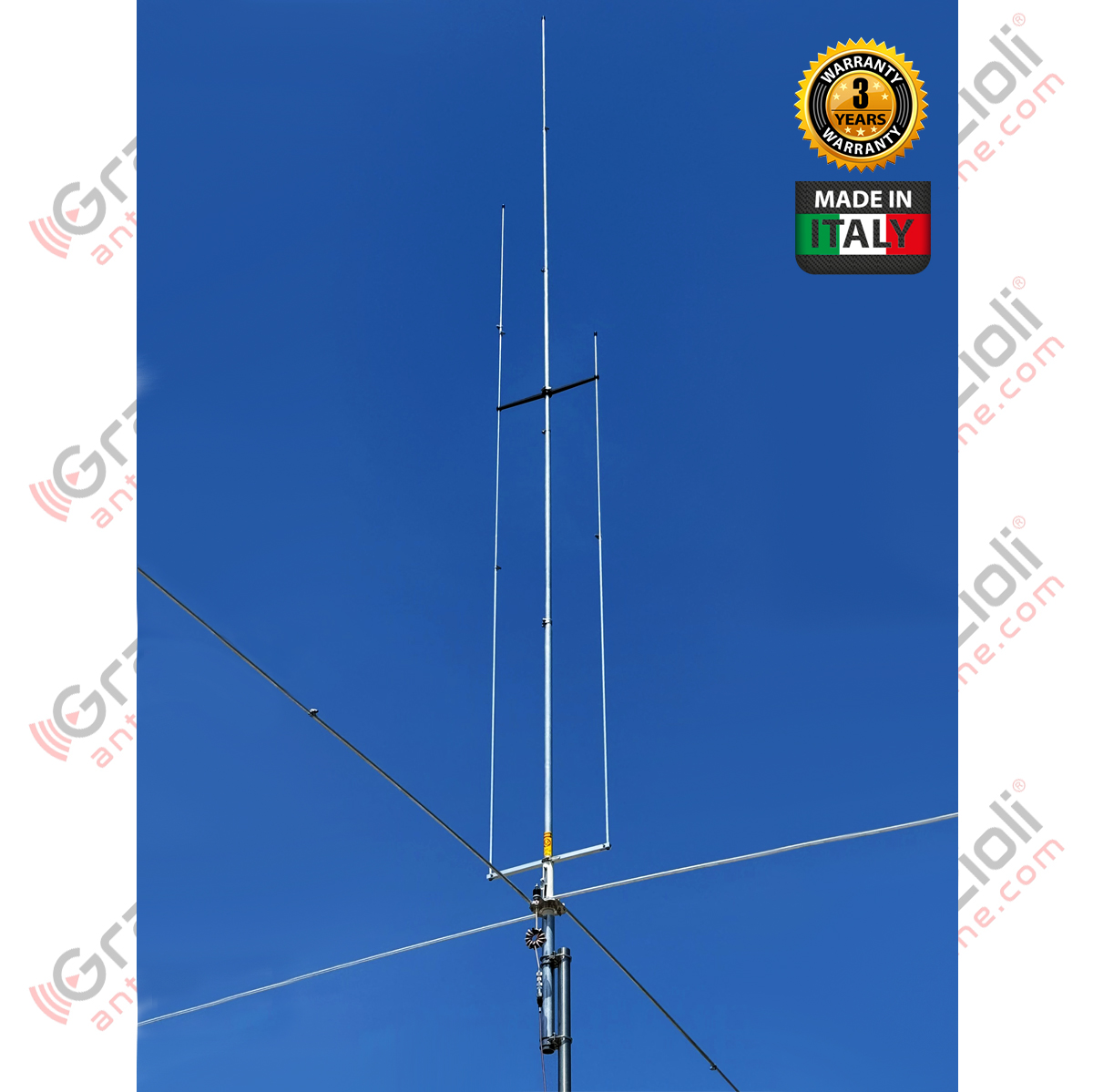
Vertical Tri-band 1/4 λ Ground Plane
HF 20, 15, 10m
Powered at the base
Max Input Power: 3 kW
Total height: 5.63 m
Antenna weight: 5 kg
In stock
Main Features
Vertical tri-band 1/4 λ Ground Plane base fed antenna for bands: 20, 15, 10 m.
Robust construction in AW6063-T66 aluminium alloy and CNC machined parts from solid stock.
Supplied with high-quality 304 and 316 stainless steel fasteners for long rust-free operating life.
High input power, up to 3 kW continuous All-mode.
Detailed assembly manual and serial number that identifies the production batch and construction data.
Supplied with an original FAIR-RITE USA FT240-43 ferrite toroid for building an efficient choke to be installed near the connector.For our tubes, we used the best material that can be used for antenna construction; it is the Aluminum, Magnesium and Silicon alloy named AW6063-T66, hardened to the T-66 state. It gives the stylus exceptional strength, which is made by extrusion and then cold-drawn.
Robust construction. The central stylus uses tubes with a diameter of 29x1.5mm at the base, and a diameter of 16 × 1.25 mm at the tip, whilst the side and radial stubs of theground plane are made of telescopic tubes with diameters of 13 and 10 mm.
The ground level ground consists of four horizontal radials each approximately 2.4 metres long, and the vertical stubs are held in position by 2 arms, the first connected to the base of the stalk is made of aluminium tubes with a rectangular cross-section machined using CNC, and the other made of thermoplastic material, in the upper section.
All hardware is made of stainless steel, the tubes are secured with robust, quality stainless steel AISl-316 clamps, brackets, hardware, and U-bolt and V-bolt U-bolts are made of AISl-304 stainless steel.
| Electrical Data | Mechanical Data | |||||
|---|---|---|---|---|---|---|
| Type | Ground Plane 1/4 λ with parallel stubs | Materials | Aluminum Alloy AW6063-T66 hard drawn tube, Fiberglass, Brass, PTFE. All hardware are made of SS AISI-304 and 316 | |||
| Frequency Range | HF 20, 15, 10m | Wind surface area | 0,21m2 | |||
| Impedance | 50Ω Umbalanced | Wind survival (no ice) | 130 Km/h | |||
| Radiation Type | Omnidirectional | Total Height5,63m | ||||
| Polarization | Linear – Vertical | Stylus Lenght | 5,05m | |||
| Gain | 0 dBd – 2.15 dBi | Radial Length | 2.4 m | |||
Bandwidth with | SWR 2:1 | |
20, 15 full band, 10m > 1.2 MHz | Mounting mast bracketø 40-52 mm | |||
| Bandwidth SWR | ≤1.5:1 (Typical) | Antenna Net Weight | 5 Kg | |||
| Imput | Power3kW | continuos | All-Mode Package dimensions14x14x145 cm | |||
| Feed system | Direct – connected to DC ground | Weight in pack | 6.35 kg | |||
| Imput connector | UHF female - PTFE insulator, gold plated centre pin | |||||
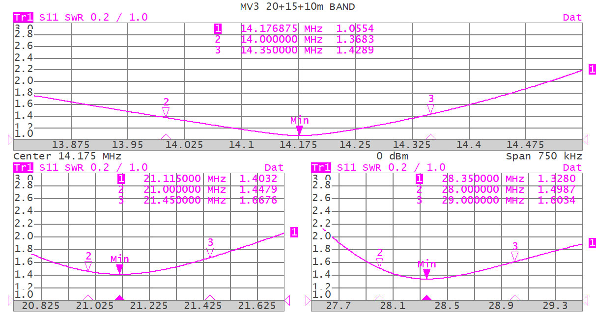 Typical SWR diagram in 20, 15 and 10m at 8 meters above ground
The basic idea was to make an efficient antenna, without using traps that reduce efficiency, and without using impedance transformers that limit the applicable power.
Based on these principles, we have developed the MV3, which, by utilising resonant elements (stubs) parallel to the central element, has enabled us to create an antenna that is efficient across all the bands it covers.
A high performance tri-band
MV3 by Grazioli antennas is a vertical HF tri-band 1/4 λ Ground Plane which operates on the following bands: 20, 15, 10 metres.
It is an entry-level antenna, lightweight and robust, which does not require any bracing, and is the solution best suited for performance, lightness (just 5 kg) and is suitable for those installations that require a low visual impact.
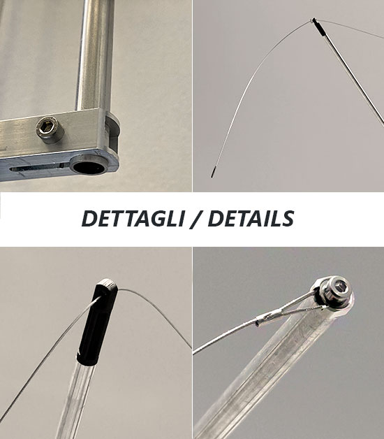
It has 4 radial earthing wires, each measuring 2.4 m in length + one radial in a single run (previously used on the MV7) in cord made of 316 stainless steel, which ensures perfect operation of all the strips even for installations located in all bands even for installations located near the ground or on the roof.
This device known as DBFC an acronym for “Dual Band Folded Counterpoise” makes this system unique in its kind and avoids the use of radial loaded cables which would cause losses, or the installation of radial strings to be arranged on the roof which might be difficult to install and secure.
MV3 is a “RESONANT” antenna and therefore powered directly without the use of adapters or transformers for impedance which would introduce losses and would would limit the power that can be applied, is equipped with inductance at high impedance which causes a short circuit in DC, discharging to earth any interference caused by events in the atmosphere and/or discharges electrostatic.
The antenna is made from tubes of medium cross-section and thickness, whilst the components made of aluminium are machined from solid stock using CNC machines, the cross-pieces which spacer the stubs are made of thermoplastic material moulded by injection moulding and protected against UV rays, and is supplied with an FT240-43 toroid from FAIR-RITE USA, for the construction of an efficient choke to be installed immediately below the connector.
NOTE:
If used in extremely windy areas, bracing with non-conductive cables/ropes is recommended.
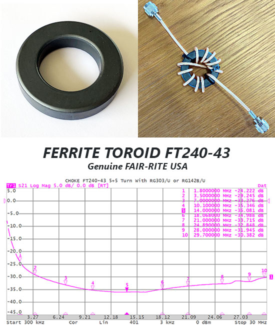
The RF choke for attenuating common mode currents
Now supplied with the MV6 is an original FAIR-RITE Made in the USA FT240-43 ferrite toroid for “Home Made” construction of your high-performance Choke. This arrangement allows you to significantly attenuate common mode currents in the HF band (1.8-30MHz), which could reduce the performance of your antenna.
Material not supplied at customer's expense for fabrication:
- No.2 PL259 connectors suitable for the type of cable you intend to use.
- (1 PL259 + 1 SO239 in case of using plastic protection box).
- Approximately 1.2m of good quality coaxial cable, such as RG58 for continuous powers up to 300 Watt AWG @ 30MHz, or RG142BU in Teflon for continuous powers up to 1500 Watt AWG @ 30MHz.
We absolutely discourage the use of cables with FOAM foam-type dielectric (white spongy dielectric) because they cannot be wrapped around the toroid without compromising its electrical characteristics.

UHF connector
The antenna connector is not the commercial SO-239 type used by most manufacturers. Our connector is designed and built directly by ourselves; it has a true 50 Ohm characteristic impedance and is rated up to 500 MHz. We have created a reliable connector capable of withstanding 5 kW of continuous RF power at 30 MHz and greater than 3 kW at 50 MHz.
The body is made of CW614N nickel-plated brass, while the pin is plated in 24K gold to avoid oxidation and is equipped with a 4-fin insulator that maintains its centring and elasticity to avoiding contact losses.
The insulating material is PTFE, one of the best insulators due to its exceptional electrical and thermal properties (low dielectric constant and reduced loss factor, operating temperature from -100 to +260 °C). The assembly is protected by a special elastomer hood that prevents water and humidity infiltration.
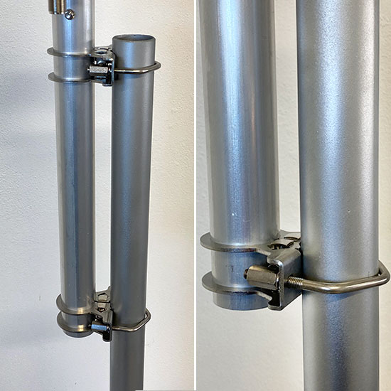
The anchor bracket
Is made of 2.5 mm-thick AISI 304 stainless steel and is attached to the antenna tube by means of a clamping system, creating an extremely robust mechanical lock.
The mast coupler is consists of an M6 V-Bolt in AISI 304 steel and column nuts for easy, secure tightening.